as
CAN Bootloader Introduction
Automotive E/E architectures are undergoing a major change: the powertrain is moving from combustion to electric, advanced driver assistance is close to a standard feature, and the Tesla-style “ship the hardware first, iterate the software later” model pushes every supplier to make every ECU OTA-capable.
This article does not discuss the cloud side of OTA. It focuses on the most basic building block: traditional MCUs in a car mostly communicate over CAN, so how is a CAN bootloader running inside such an MCU typically designed, and how does it work?
A bootloader has two main jobs:
- boot: validate and start the APP after power-on;
- loader: answer diagnostic update requests and program a new APP into flash.
Booting the APP
The program of an automotive MCU usually lives in flash. After reset the MCU fetches its first instruction from a fixed flash address; this initial region is the boot region that holds the bootloader, while the remaining flash is the app region for the application. The figure below shows a simple example; the red areas mark the boot and app interrupt vector tables.
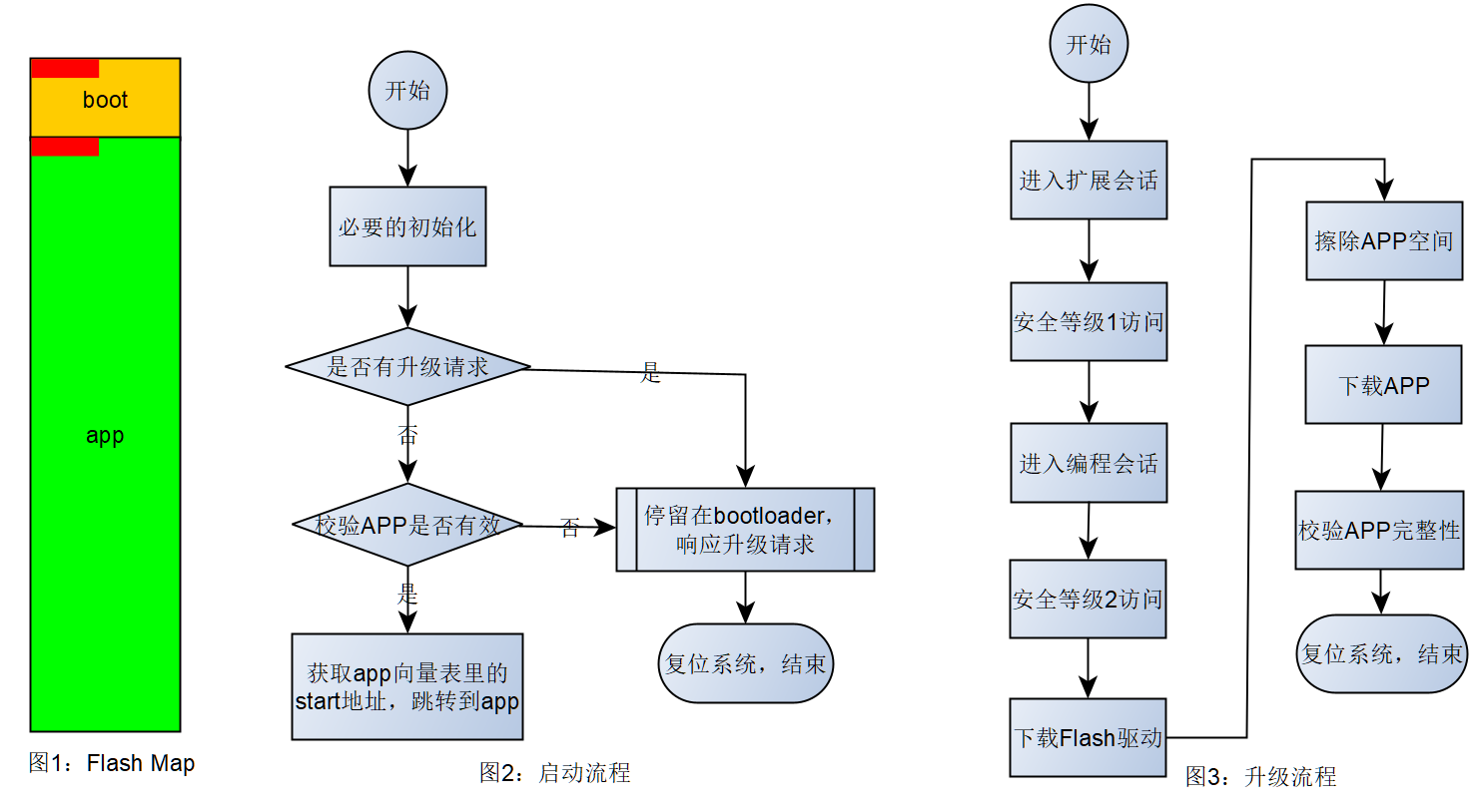
The first entry of the vector table is the reset vector, holding the address of the startup entry (usually written in assembly), which prepares the C runtime: it initializes the data and bss sections and the stack, then calls main.
Step (2) in the figure shows the normal boot-to-APP path. It is deliberately kept as simple as possible so that control is handed to the APP quickly and startup time stays short.
Updating the APP Through the Loader
The loader inside the MCU is a UDS (Unified Diagnostic Services) server. It answers a sequence of UDS requests issued by the tester (client) to update the APP, as outlined in step (3) of the figure. The exact services used in each step are shown in the lab below.
A bootloader project normally consists of three build targets:
- bootloader project: linked to the start of flash, handles startup and flashing;
- Flash Driver project: a standalone flash erase/program driver that is downloaded to RAM only while flashing;
- Application project: the actual application.
Lab: QEMU Versatilepb Bootloader Demo
The following lab uses the QEMU Versatilepb virtual machine to walk through the three targets and a complete update cycle. The platform is already integrated in this repository under app/platform/qemu, so no extra download is needed.
First set up the toolchain as described in Build environment setup, then double-click Console.bat in the project root to open the ConEmu terminal.
# app tab: build the PC-side tools
D:\repository\as>scons --app=Loader
D:\repository\as>scons --app=CanBridge
D:\repository\as>scons --app=CanDump

# enable CAN FD mode, up to 64 data bytes per frame
D:\repository\as>set LL_DL=64
D:\repository\as>scons --cpl=QemuVersatilepbGCC --app=VersatilepbFlashDriver
# the first build downloads gcc-arm-none-eabi and takes a while
D:\repository\as>scons --cpl=QemuVersatilepbGCC --app=VersatilepbCanApp
D:\repository\as>scons --cpl=QemuVersatilepbGCC --app=VersatilepbCanBL
Signing is performed automatically as an SCons post-action, no manual step required: the APP is signed with crc16-v3 at sign address
0x3FE80; the flash driver gets a crc16 at offset 4096. Both produce*.s19.sign.
Optionally change the log line of main in app/app/main.c so the new build is easy to recognize:
int main(int argc, char *argv[]) {
  ASLOG(INFO, ("application v2 build @ %s %s\n", __DATE__, __TIME__));
Then rebuild the APP:
D:\repository\as>scons --cpl=QemuVersatilepbGCC --app=VersatilepbCanApp
Start the virtual machine and the bus bridge:
# app tab: start QEMU (its second UART is exposed as a serial CAN channel)
D:\repository\as>scons --cpl=QemuVersatilepbGCC --app=VersatilepbCanBLRun
qemu-system-arm.exe: -serial tcp:127.0.0.1:9000,server: info: QEMU waiting for connection ...

# sim tab: bridge the QEMU serial CAN onto the v2 virtual bus
D:\repository\as>build\nt\GCC\CanBridge\CanBridge.exe -d qemu -d simulator_v2
# tool tab (optional): bus monitor / sniffer
D:\repository\as>build\nt\GCC\CanDump\CanDump.exe
Back in the app tab, the bootloader validates the image and starts the old APP (no “v2” yet):
INFO    :bootloader build @ Dec 15 2021 19:26:46
INFO    :application is valid
INFO    :application build @ Dec 14 2021 22:55:11
In the boot tab, start the update (add -v to see every UDS request/response):
D:\repository\as>build\nt\GCC\Loader\Loader.exe -a build\nt\QemuVersatilepbGCC\VersatilepbCanApp\VersatilepbCanApp.s19.sign -f build\nt\QemuVersatilepbGCC\VersatilepbFlashDriver\VersatilepbFlashDriver.s19.sign -l 64
Full-system simulation is software-timed and slower than real hardware; if a CanTp timeout happens occasionally, just rerun the command. To get familiar with the flow first, the host CanBL demo runs directly on Windows; see BL.md, section 6.
On success the boot tab prints:
loader started:
enter extended session          progress  0.10%  okay
level 1 security access         progress  0.30%  okay
enter program session           progress  0.40%  okay
level 2 security access         progress  0.60%  okay
download flash driver           progress  3.62%  okay
erase flash okay
download application            progress 95.91%  okay
check integrity                 progress 96.01%  okay
ecu reset                       progress 99.00%  okay
loader exited without error
                                progress 100.00%
The app tab then shows the new version string, confirming that the update succeeded and the new APP is running:
INFO    :bootloader build @ Dec 15 2021 19:26:46
INFO    :application is valid
INFO    :application v2 build @ Dec 14 2021 21:47:05
With -v you can see that the whole update is an ordered sequence of UDS services:
enter extended session
 request service 10:  TX 10 03               RX 50 03 13 88 00 32
level 1 security access
 request service 27:  TX 27 01               RX 67 01 CF 71 2C 84
                      TX 27 02 B7 E2 6A F7   RX 67 02
enter program session
 request service 10:  TX 10 02               RX 50 02 ...
level 2 security access
 request service 27:  TX 27 03 / 27 04 ...
download flash driver
 request service 34:  TX 34 00 44 ...        RX 74 20 02 02   # RequestDownload
 request service 36:  TX 36 01 ...           RX 76 01         # TransferData
 ...
 request service 37:  TX 37                  RX 77            # RequestTransferExit
download application
 request service 31:  TX 31 01 ...           RX 71 01 ...     # RoutineControl: erase / check
 request service 34 / 36 / 37 ...                                              # download app
check integrity
 request service 31:  TX 31 01 ...           RX 71 01 ...     # RoutineControl: CRC check
ecu reset
 request service 11:  TX 11 01               RX 51 01         # ECUReset
The UDS services involved are, in order: 10 (SessionControl), 27 (SecurityAccess), 34 (RequestDownload), 36 (TransferData), 37 (RequestTransferExit), 31 (RoutineControl: erase and check), 11 (ECUReset).
Memory Layout of the Three Targets
In this demo, Versatilepb address range 0x00008000 ~ 0x00140000 (1248 KB) is emulated as flash and 0x00140000 ~ 0x00180000 (256 KB) as RAM. The QEMU machine physically has only RAM; part of it is simply treated as flash.
The bootloader linker script linker-boot.lds:
MEMORY
{
   FLASH        (rx)   : ORIGIN = 0x00008000, LENGTH = 224K
   APPCODE      (rx)   : ORIGIN = 0x00040000, LENGTH = 1024K
   FLSDRV       (rwx)  : ORIGIN = 0x00140000, LENGTH = 4K
   RAM          (rwx)  : ORIGIN = 0x00141000, LENGTH = 252K
}
0x00008000 ~ 0x00040000 is the boot region; the app region starts at 0x00040000. The matching app script linker-app.lds:
MEMORY
{
   FLASH        (rx)   : ORIGIN = 0x00040000, LENGTH = 1024K
   RAM          (rwx)  : ORIGIN = 0x00140000, LENGTH = 256K
}
And the flash driver script linker-flsdrv.lds:
MEMORY
{
  FLASH        (rwx)  : ORIGIN = 0x00140000, LENGTH = 4K
}

ENTRY(FlashHeader)

SECTIONS
{
    .text :
    {
      *(.rodata*)
      *(.text*)
    } > FLASH
}
Note that the bootloader RAM starts 4 KB later than the app RAM. Those 4 KB (0x00140000 ~ 0x00141000) are reserved for the flash driver that is downloaded into RAM; bootloader plus flash driver together perform the update. The bootloader-side partition configuration is in BL.json.
Why the Flash Driver Is a Separate Target
This is a functional-safety measure. Code may contain bugs, and an MCU may run wild under electromagnetic interference. If flash erase/program instructions were statically linked into the resident code, an accidental execution could erase the boot or app region and brick the ECU. Two common protections are used in the industry:
- Dynamic download (used here): the flash driver normally does not exist on the ECU; only after entering the programming session and passing security access is it downloaded via UDS into a designated RAM area, executed, and discarded;
- Obfuscated storage: the machine code of the flash driver is bit-inverted or encrypted in flash and reconstructed in RAM before use, so no directly executable erase/program instruction ever exists in flash.
Partitioning and linking are the hard part of a bootloader port. Linking an ordinary project to a fixed address is easy with an IDE; the tricky part is producing a build that contains nothing but the flash driver. Link control differs between toolchains, so consult your compiler’s documentation for entry points and section placement - in embedded development the program entry is not necessarily main. The script above rewrites the entry with ENTRY(FlashHeader) and places rodata at the start of FLASH; in Flash.c, the only const object in the whole project is FlashHeader:
const tFlashHeader FlashHeader = {.Info.W.MCU = 1,
                                  .Info.W.mask = 2,
                                  .Info.W.version = 169,
                                  .Init = FlashInit,
                                  .Deinit = FlashDeinit,
                                  .Erase = FlashErase,
                                  .Write = FlashWrite,
                                  .Read = FlashRead};
Therefore FlashHeader sits exactly at 0x00140000. The bootloader interprets the memory at that address as a tFlashHeader, obtaining the Init/Erase/Write/Read function pointers and version information, and can run consistency checks against it.
This article only covers the main path. After completing the QEMU lab you should have a solid basic understanding of how a bootloader works. For the BL module configuration itself (A/B partitions, metadata, the three signature formats, etc.) see the reference document BL.md.
Host CanBL Demo
If the QEMU full-system simulation gives you trouble, CanBL can also run directly on the Windows host with an emulated flash. The complete procedure is in BL.md, section 6.
QEMU GDB Debugging
1. Start QEMU with the GDB server enabled
scons --cpl=QemuVersatilepbGCC --app=VersatilepbCanBLRun gdb
This appends -gdb tcp::1234 -S to the QEMU command line: the virtual machine freezes at the first instruction and waits for GDB.
2. Connect with arm-none-eabi-gdb
Open a new terminal:
arm-none-eabi-gdb.exe build/nt/QemuVersatilepbGCC/VersatilepbCanBL/VersatilepbCanBL.exe
Inside GDB:
(gdb) target remote localhost:1234

# e.g. single-step until the PC leaves the reset vector
while $pc != 4
  stepi
  print/x $pc
end